Compact hardware
Review the panel, touch, cover and mounting allowance together for a compact enclosure. The complete assembly thickness matters as much as the panel alone.
BINTU / Flexible AMOLED solutions
Integrate a flexible OLED display module into your OEM hardware with BINTU Global. We review AMOLED module selection, FPC, cover glass and touch integration against the product design; curvature and assembly requirements need project-specific validation. For requirements beyond the selected module, review our custom OLED engineering approach.
Why flexible AMOLED
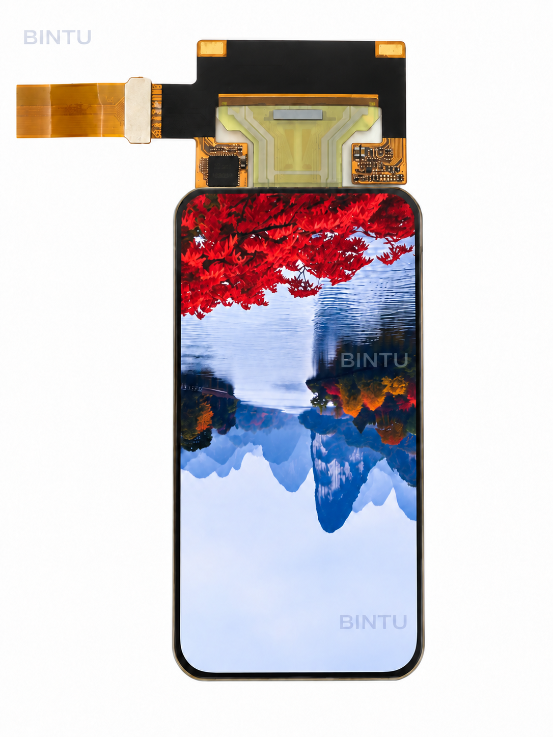
Flexible OLED display solutions are relevant when the visible surface, enclosure or internal routing needs more coordination than a standard display installation.
Review the panel, touch, cover and mounting allowance together for a compact enclosure. The complete assembly thickness matters as much as the panel alone.
Explore flat, curved, circular or custom-shaped directions against the available panel platform. Final geometry and any permitted curvature require confirmation.
Bring FPC routing, connector location and the host connection into the selection review early, before the enclosure and board layout become fixed.
Custom flexible AMOLED / engineering coordination
BINTU supports display selection and coordination across the display, touch, cover, FPC and product structure. The scope is confirmed for the chosen platform and project.
Customization options
Compare the required display window, aspect ratio and resolution with available platforms. A different active area may require a different panel rather than a simple module modification.
Review the panel envelope, visible opening and intended shape together. Curved or distinctive layouts need a clearly defined geometry and panel-specific feasibility review.
Coordinate FPC length, exit position and routing direction with the enclosure and host board. Account for clearance, assembly access and connector orientation.
Review the cover outline, display window and cosmetic surface against the OLED and touch stack. Cover geometry and available installation space need to agree.
Discuss the interaction requirements, touch stack and bonding approach together. Application-specific touch behaviour must be evaluated rather than inferred from the display type.
Confirm the host interface and connector requirements for the selected reference. Review positioning and connection details before the hardware layout is approved.
Integration capabilities
Align the active area, outline, opening and intended curvature. Distinguish the visible region from the panel envelope and the complete assembly dimensions.
Coordinate OLED, touch and cover glass as one optical stack. The proposed combination and application requirements guide the engineering review and sample evaluation.
Review the panel, bonding, touch, cover and supporting structure within the available product space. A panel thickness value is not a complete stack definition.
Check the bezel, enclosure, mounting and internal clearance together. Provide mechanical drawings or a dimensional brief to identify potential conflicts early.
Relate the FPC route and connector orientation to the board position and assembly sequence. Evaluate the physical connection alongside the interface requirements.
Evaluate viewing, interaction and physical fit against the agreed project brief. The final configuration is confirmed through the relevant documents and samples.
Final geometry, interface, touch stack, cover glass and mechanical details are confirmed case by case during project evaluation.
Form factor / product fit
Provide the display opening, enclosure space and board position. Review the active area, outline, stack and FPC clearance before selecting a reference.
Define the curvature and whether it is fixed or moves during use. Panel capability, bonding and mechanical support require a coordinated review.
Use the actual active area and outline to plan the window and UI. Shape, resolution and customization availability depend on the selected platform.
Relevant AMOLED products
Use the AMOLED Catalog to compare display size, resolution, structure, backplane and shape. A Public Basic Datasheet supports preliminary dimensional selection; it does not replace the full engineering package or confirm custom integration feasibility.
Engineering process
Share the application, display window, resolution and enclosure constraints. Compare a suitable reference with the product requirements and identify gaps.
Review display, touch, cover, FPC and host interfaces. Evaluate the proposed configuration using relevant engineering information and samples.
Record the approved configuration and remaining project requirements for production preparation. Availability and project scope are confirmed directly with BINTU.
Questions before selection
Practical answers for your first display review.
BINTU supports project review of display size and active area, outline, FPC routing, connector position, touch, cover glass and mechanical integration. The starting panel determines which changes are feasible: a custom assembly does not automatically mean a new active area or resolution is available. Send the target display window and enclosure constraints so that a suitable platform and the required engineering work can be identified.
FPC length, exit direction, routing and connector orientation can be evaluated against the host board and enclosure. Useful inputs include the connector specification, board location, available clearance and assembly direction. BINTU coordinates these requirements with the display configuration; the final electrical connection and mechanical layout need engineering confirmation before the assembly is approved.
Curved cover glass, touch and bonding can be reviewed as a complete assembly. Specify the intended curve, display window, cover outline and thickness allowance. A curved cover surface alone does not establish that the OLED panel may be bent to the same shape. Panel limits, bonding compatibility and support requirements must be checked for the selected configuration.
A flexible construction does not by itself confirm repeated folding, a minimum bend radius or an unrestricted bending direction. Installation curvature and movement during use are different requirements. Describe how the screen will be mounted and whether it will move in service. The applicable limits and validation method must come from the selected panel documentation and project evaluation.
The review connects active area and outline with the display opening, touch and cover stack, bezel, mounting space and FPC route. BINTU supports coordination of these interfaces so that the front surface and internal hardware are considered together. Relevant engineering documents and sample evaluation are used to confirm the proposed configuration before production preparation.
Provide the application, target size and resolution, visible window, enclosure drawing, thickness allowance and host interface requirements. Include touch and cover requirements and a preferred BINTU Reference when available. An incomplete brief can still start a discussion; BINTU can help identify the remaining inputs needed for selection. Detailed specifications and drawings are provided following project review through [email protected].
Start your engineering discussion
Send the display window, enclosure constraints and integration priorities. Detailed specifications, drawings and engineering documentation are provided following project review.